
LeapPad Explorer Reversing
 One drawback of all of my recent work and travel is less time for other pursuits. Case in point: It has been a long, long time since I did any serious hacking. And like any habit, after a while, the ‘jones’ gets to be too much to bear.
Last night I succumbed.
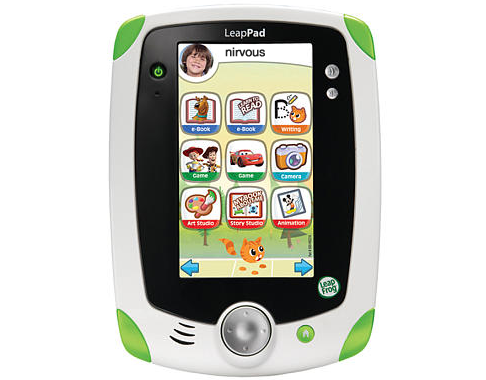
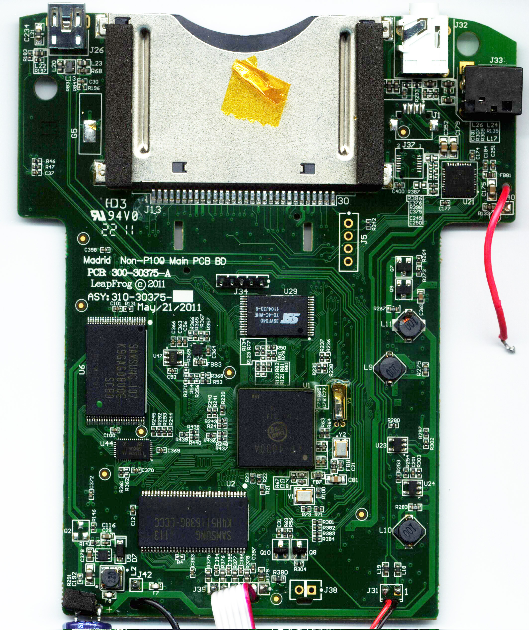
I found out from the good people on irc (freenode #Didj) that our friends at LeapFrog have released a 3rd generation of Linux-based handheld toys powered by the now-venerable ARM926EJ-S-based LF1000 CPU (aka Pollux): The new device, a tablet handheld called LeapPad Explorer (code name Madrid) has a 5-inch LCD, a built-in camera, boots off of eMMC connected to the SD controller (instead of NAND Flash as in prior devices) and adds an accelerometer to the mix. The mini tablet form-factor makes this an interesting candidate for alternate uses. (Portable o-scope or logic analyzer? G-force meter? True-to-scale tall-screen arcade emu handheld?)
Curiosity got the better of me and before I knew it I was in my local big-box retailer shelling out hard-earned dinero for fresh pristine hardware, ripe for reversing.
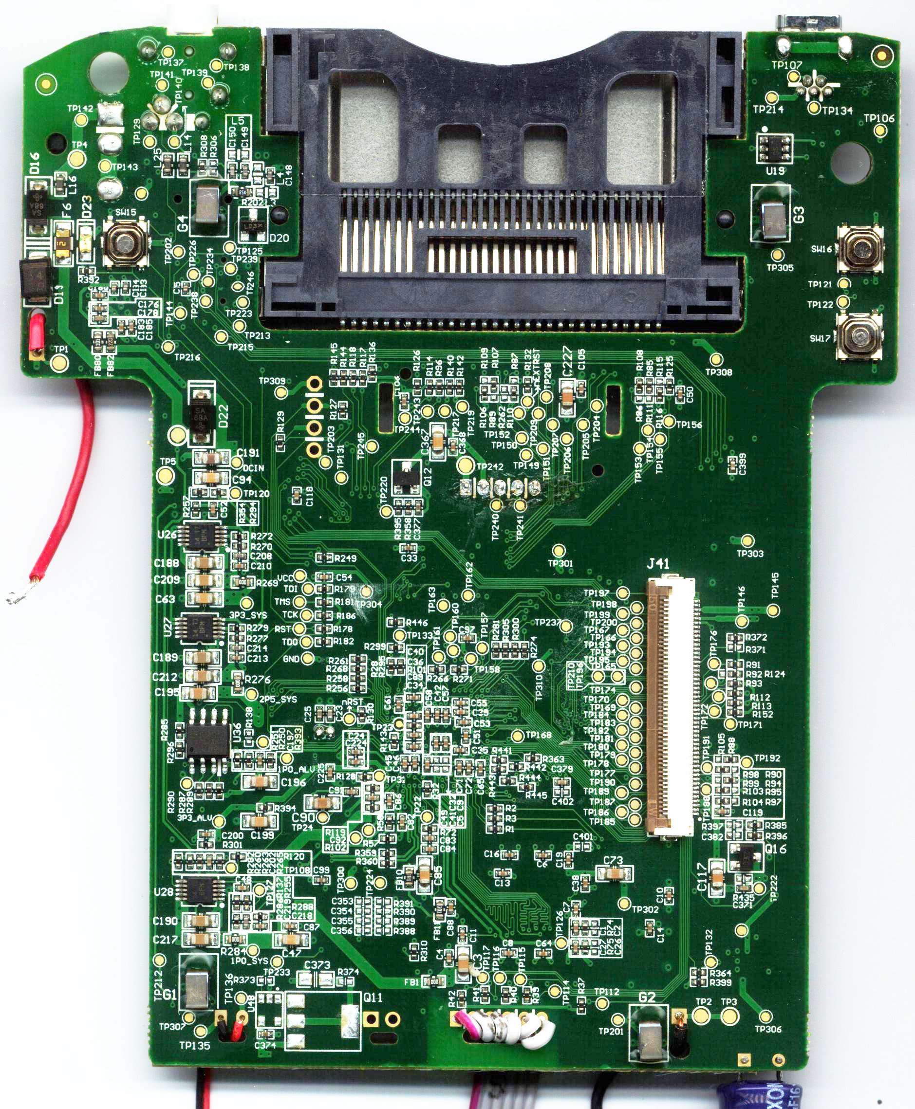
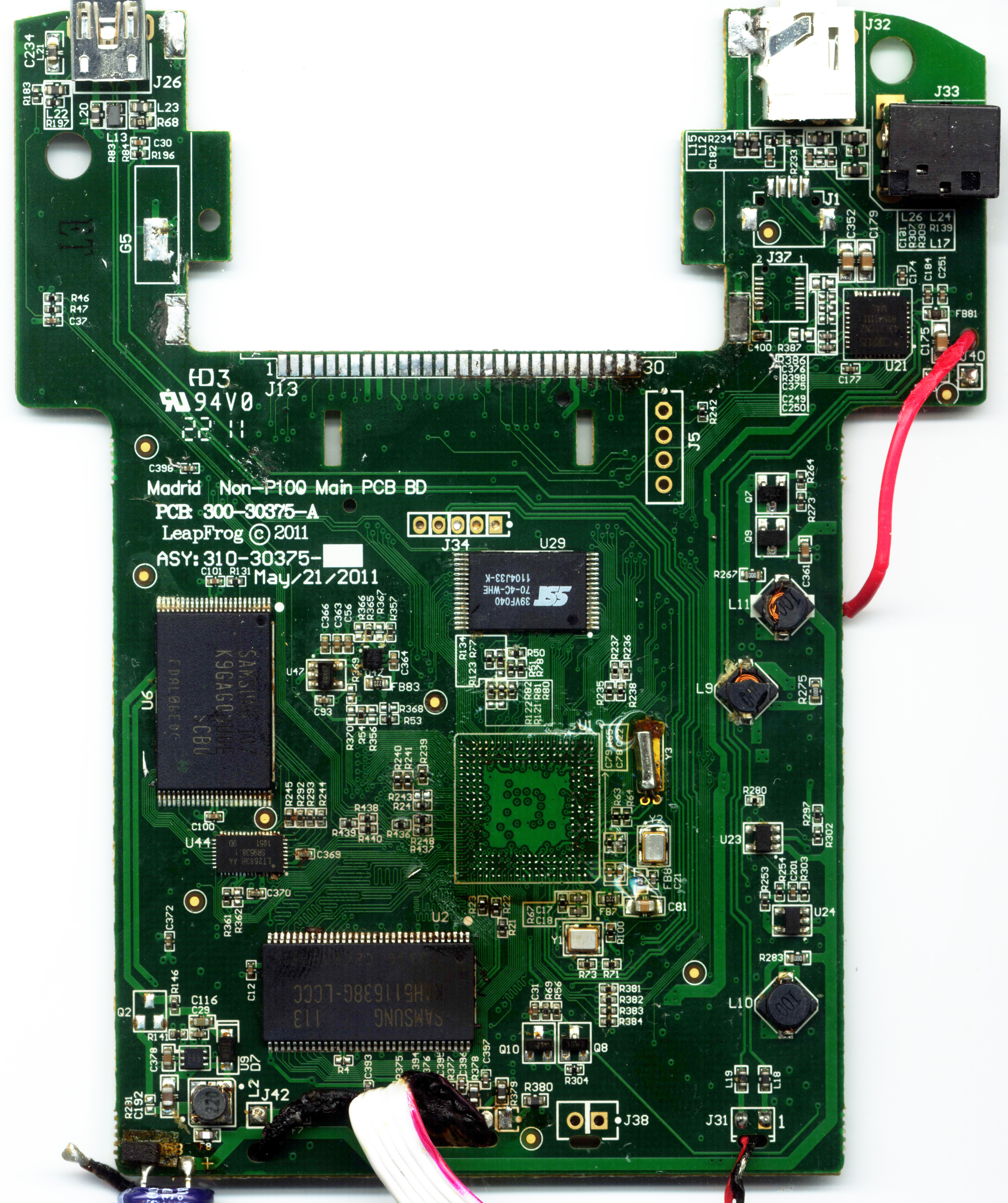
A night’s work ensued, including sweeps with a continuity checker, a little de-soldering, some conformal coating stripper to soften the epoxy around the CPU and, finally, some hot-and-heavy action with a heatgun to reflow and remove the CPU. (The epoxy made chip-removal less than optimal, so some of the BGA balls didnt make it, but at least we can follow the traces.)
![]()
What we've found thus far:
UART Serial on the cartridge socket. UART is on the same pins as on previous LF1000 devices, which claude first documented on Didj way back when; so Moogle's DJHI breakouts will probably work fine. (I haven’t tested this yet) Edit: If at first the device doesn't boot with DJHI inserted, simply re-seat the DJHI and try again.
UART Serial on J5 – VCC, Rx, Tx, Gnd - this looks to be similar to the J5 on the Leapster Explorer.
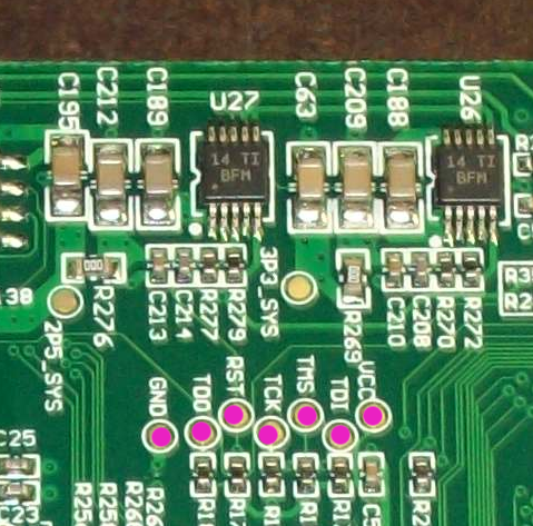
JTAG – nicely labeled, right there on the silkscreen – and a big shoutout and props to the LeapFrog engineer(s) responsible for labeling the pads. Thank you. Your spot in heaven is assured. :)
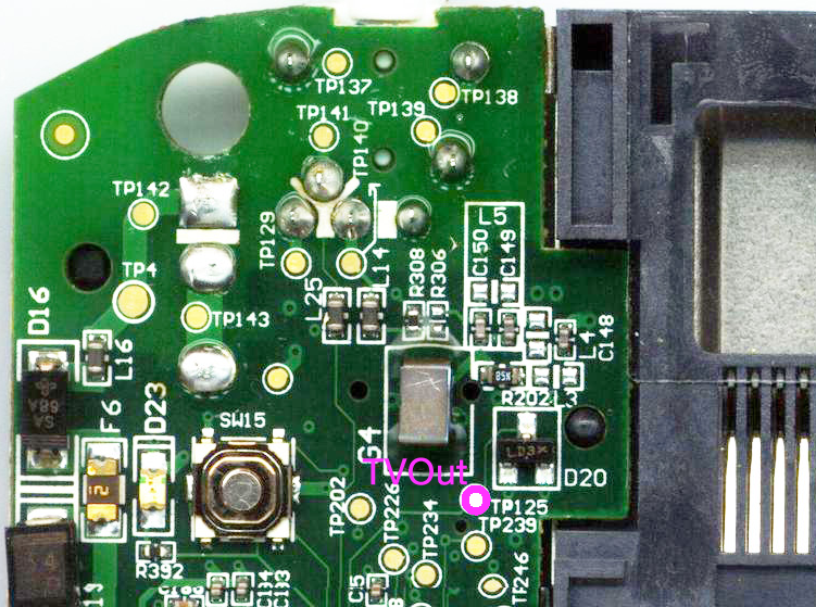
TVOut – TP125 is linked to good ol’ BGA grid square A2. Having gotten composite video working on Didj and Leapster Explorer devices I have a soft spot in my heart for this test pad. (Traced, but not tested, stay tuned...)
USB - The pin header, J34, to which the camera was attached, is USB Device. Pins 2 and 3 on J34 are D+ and D-. Pin 4 is GND and Pin 5 (square) is VCC.
Here are the mainboard scans for the front and rear (and the rear following removal of the CPU and cartridge socket).
Enjoy!

Images/content licensed under a Creative Commons Attribution-ShareAlike 3.0 Unported License.
n-
 nirvous
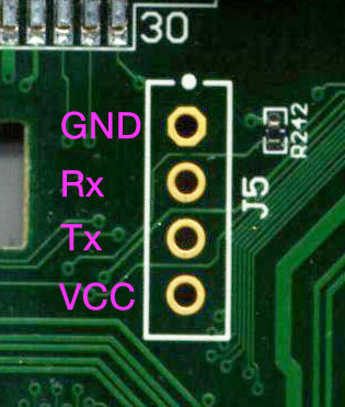